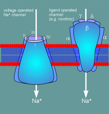
 Voltage-operated ion channels have a very different structure from ligand
operated ion channels.
  Voltage-operated ion channels have a very different structure from ligand
operated ion channels.
A large portion of ligand operated ion channels is extracellular (~50%), whereas the bulk of a voltage operated ion channel is in the membrane or intracellular.
The voltage operated channels are constructed from 4 identical subunits (as in the voltage-operated K+ channel) or from 4 domains structurally similar to the K+ subunit, but found within one large protein.
This latter situation is the case for voltage-operated Na+ and Ca2+ channels.
A number of functional domains have been identified within the voltage-operated ion channels.
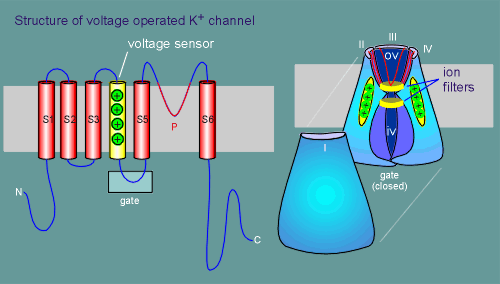 These
have been illustrated for the voltage-operated K+ channel in the diagram to the left.
Each subunit has 6 transmembrane regions (S1 to S6), one of which has 4 positively charged amino acids (lysines or arginines) and functions as a voltage sensor (S4).
Four subunits (labelled I to IV) make up a functional ion channel (subunit I has been pulled away so you can see inside the channel).
The ion pore itself is formed by a loop between transmembrane region S5 and S6, labelled the P loop (P for pore).
This is similar to how the pore is formed for glutamate receptors (review the glutamate receptor pore?)
The channel has a large open outer chamber, referred to as the outer vestibule (ov) and an inner chamber or inner vestibule (iv).
The P loops can be seen looping down into the outer vestibule to form the ion pore (red lines, most visible with subunit III).
Between the outer and inner vestibule is a narrow section in which ion selective filters are located, one on the extracellular side of the narrowing between the vestibules and the other on the intracellular side (review ion filters in nicotinic receptor?)
The filters are primarily responsible for ion selectivity of the channels ..... this has nicely been demonstrated by point mutations which have converted a Na+ channel into a Ca2+ preferring channel.
On the intracellular side is a gate which opens when the membrane depolarizes.
At least part of this gate is constructed from the intracellular loop between S4 and S5.
How membrane depolarization might translate into an opening of this gate is explained below.
The fourth transmembrane region (designated S4) contains lysines and arginines.
This is unusual for a transmembrane region because lysine and arginine possess positively charged side chains, which are incompatible with the hydrophobic environment in the membrane.
This has led to the idea that S4 may be the voltage sensor.
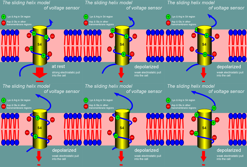 One model for how this might work is called the sliding helix model.
Imagine S4 curling through the membrane as an alpha helix (blue line figure; yellow cylinder is there for the blue line to wrap around to emphasize the alpha helix nature of S4).
The positive charges of the lysines and arginines would form ion pairs with negatively charged amino acid side chains in other transmembrane regions (S1, S3, S3, S5 or S6).
At rest S4 is held in position in the membrane through the ion pairing.
The high negative charge inside the cell (-70 mV) is trying to pull S4 into the cell (red arrow).
Suddenly, with depolarization, the electrostatic pull into the cell is far less and S4 starts to curl out of the cell (the sliding helix).
It continues to curl out until the positively charged lysines and arginines form new ion pairs, at which point it stabilizes in the new position until the cell repolarizes.
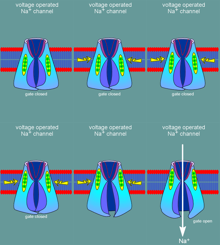 The idea is that the movement of the voltage sensor would induce opening
of the ion pore (just like binding of ligand to a ligand operated ion channel induces
channel opening).
Shown to the left is a representation of a voltage operated ion channel with one of the repeat domains removed so you can see inside the channel.
Note the red "P" domains forming the ion channel.
With depolarization (yellow arrow) the voltage sensor moves towards in the extracellular direction.
It is believed that all four S4 voltage sensors must move in order to induce opening of the gate on the intracellular side of the channel.
Exactly how the movement of the sensors is transduced into gate opening is not known.
With opening of the gate Na+ ions are free to enter the cell thus causing a further depolarization.
After opening it is believed that the pore is then spontaneously closed by an intracellular domain of the ion channel which physically blocks the channel (plugs it) until the gate spontaneously closes.
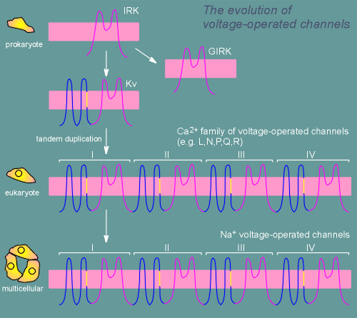 The
analysis of ion channel distribution among primative species indicates that K+ channels
were the first to evolve.
The core design of the K+ selective pore can be found in the inward rectifier K+ channel (IRK) and the closely related G protein-operated inward rectifier K+ channel (GIRK).
Gating of the latter channel is regulated by G proteins and thus by receptors coupled to G proteins.
At some point in evolution the IRK acquired 4 transmembrane segments including a segment with several positive charges, the primative voltage sensor (yellow segment in figure).
Somewhere around the emergence of unicellular eukaryotes the voltage-operated K+ channels (Kv) underwent a tandem duplication, giving rise to the Ca2+ family of voltage-operated ion channels.
At this point Ca2+ channels were used for both the creation of action potentials and for Ca2+ signaling (i.e. activation of kinases).
The Na+ channels seem to have arisen from the Ca2+ channels at the origin of multicellular animals.
The creation of voltage-operated Na+ channels permitted the specialization of rapidly conducting axons necessary for the development of a nervous system.